 |
 |
 |
 |
|

Vydáno dne 09. 02. 2020 (1511 přečtení) |
|||||||||||||||||||||||||||||||||||||||||||||||||||||||||||||||||||||||||||||||||||||||||||||||||||||||||||||||||||||||||


|
přepnout na českou verzi |

They asked me how to adjust the gain and some other parameters for their particular microphone. To tell the truth, I didn't give them much advice. From the distance, if you do not know the parameters of the microphone and you do not have the opportunity to measure and test by yourself, it is hard to give advice.
I recently started trying the next "the last" version of this transceiver, this time with an OLED display and rotary encoder control. In order not to have to deal with the problems of adapting different microphones, I decided to build a dedicated microphone, which will have a preamplifier with an operational amplifier in itself.
 | ") | ") |
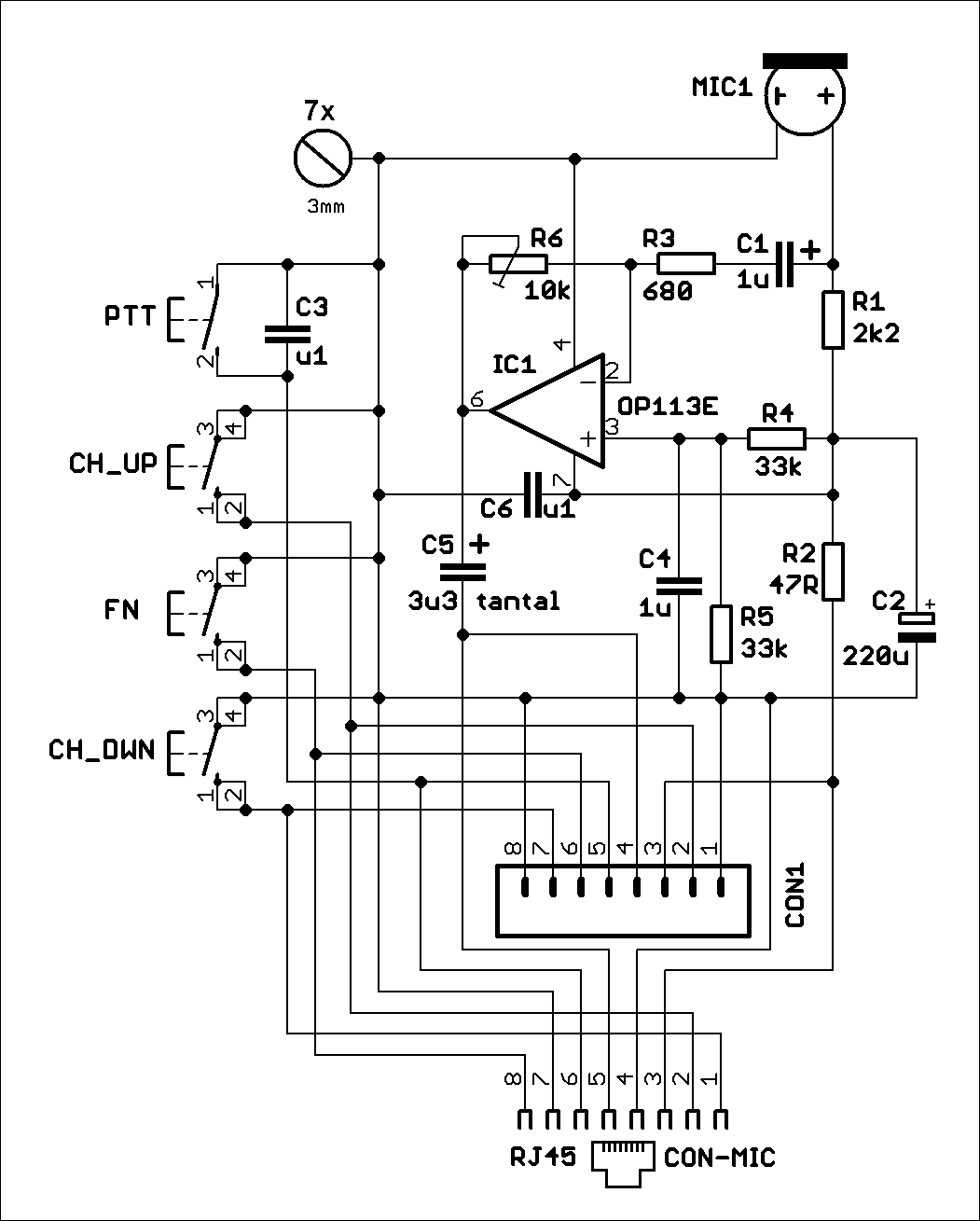
| Schema of mic with Op. Amplifier in higher resolution | check of Gerber files | check of Gerber files |
List of components (Opens in a new window.)
I used an electret "capsule" of unknown type (I feel that all these electret microphones are the same, or at least very similar) and low-noise Op. Amp. OP113E, which works with asymmetric power supply from 4.0V. Use of the OpAmp as an inverting amplifier will allow us to set the gain from zero, so we can have the output signal even lower than the electret itself. Seemingly it makes no sense, but we get a low impedance modulation signal so it is resistant from an interference.
Capacitor C5 has a relatively large value of 3.3uF to avoid cutting of low frequencies at low impedance. Because of the size, I used tantalum electrolyte. However, because I found the modulation too bass, I cut it (from about 200 Hz) using capacitor C1-1uF (monolithic, multilayer ceramics). Its value can, of course, be increased if we want to have more bass in modulation. If an electrolytic capacitor is used (for example the same as C5), the polarity must be maintained as shown in the schematic.
Use the trimmer R6 to set the required gain.
The resistor R2 slightly decreases the supply voltage of the operational amplifier, so the supply voltage of the microphone (from the transceiver) needs to be at least 4.5V.
") | ") | ") |
| Microphone - assembled | Microphone - assembled | Microphone in case |
The first version I made, used the eight-pin PSH connector (or you can solder the individual wires of the cable directly into the PCB). Then I got an idea, that if I am using an eight-pin RJ45 on the TRX, I could use it also on the microphone. Therefore, it is possible to use an uncrossed UTP cable with a length of 50 or 100 cm to connect the microphone to the TRX.
I tried the microphone with Yaesu FT-817nd. Works without problems. Of course, we need to turn down quite a lot the modulation in the transceiver settings, because this microphone gives a much higher output signal than the original dynamic microphone.
 | ||
| wiring the connector of FT-817 | ||
I designed the microphone PCB to fit into the plastic box KM26N. The TRX tuning control buttons are Omron microswitches for PCB with plastic buttons. A 90 deg Omron microswitch with plastic button is also used for the PTT button.
Jarda, ok1hdu
| Celý článek |
| Novinky |
|
07.07.2023: Update na webu DXFC Dneska jsem updatoval info na webu DXFC.
05.07.2019: Update fotoalba Do fotoalba jsem přidal pár fotografií ze:
Slovinska (červen 2019) Fotoalbum prozatím zrušeno. 05.12.2018: Update fotoalba Do fotoalba jsem přidal pár fotografií ze:
Slovinska (jaro 2018) a ze: Suchého Vrchu (zima 2005/2006). Fotogalerie je prozatím zrušena. |
| kalendář |
| |||||||||||||||||||||||||||||||||||||||||||||||||
| Radary ČHMU |
|
| Zaparkováno na: |

|
| TSL certifikát: |

|


Tento web site byl vytvořen prostřednictvím phpRS - redakčního systému napsaného v PHP jazyce.
Na této stránce použité názvy programových produktů, firem apod. mohou být ochrannými známkami
nebo registrovanými ochrannými známkami příslušných vlastníků.